Handlekurven er tom
Handlekurven er tom
Du vil motta en e-post så snart produktet er på lager!
En ukjent feil har oppstått. Prøve igjen
The Ampetronic CLS2 is the second unit in a series of induction loop drivers aimed at the demands of the electrical and audio-visual contractor.
Designed for simple discreet installation, the CLS2 is the most capable driver in its class. The ampli er is very compact, yet the most powerful unit available designed speci cally for wall mounting. All connec- tions and controls are secured behind a tamper resistant, hinged, detachable cover. Combined with its small size, the range of mounting and cabling options ensure that installation is convenient and tidy in any environment. Input options are extensive, with four independent inputs for balanced micro- phone, balanced and unbalanced line, low imped- ance and 100V - line speaker systems, plus priority alarm, doorbell or telephone connections.
Backed by Ampetronic’s standard 5 year warranty and comprehensive support services, the CLS2 is truly t and forget.
Features
Quick and simple to install
Area coverage to >400m2
Highest power Loops driver in class
4 independent con gurable inputs
Wall mounted
Metal Loss Correction
5 Year warranty
Cabling and controls behind tamper resistant cover
2 Priority alarm inputs
Free Technical support
Applications include
• Community Centres • Board rooms
• Churches
• Interview rooms
• Meeting rooms • Classrooms
Perimeter Loops – Area Coverage (maximum)
Room aspect ratio 1:1 2:1 3:1 Maximum area m2 250 310 400
For any Induction Loop System, area coverage is dependent on
several factors. Please check these assumptions and contact Ampetronic for advice if required:
• Loop must be 1-2m above or below the receiver height
• There should be no metal structures in the plane of the loop
• Suf cient voltage to drive the loop – check the cable table below
Maximum Cable Length
The CLS2 is designed for SINGLE TURN loops for optimum audio quality: • Loops with DC resistance from 0.2O
• Impedance up to a maximum of 1.3O
Maximum cable length is dependent on cable type and on the application:
Cable type
1.0mm2 copper
2.5mm2 copper
4.0mm2 copper
1.8mm2 at copper tape
Maximum Total Cable Length (m)
Normal use 49
67
70
87
Transient speech 57
85
91
101
CLS2 Product Information
INPUTS
Input 1
Input 2
Input 3
Input 4
Alert 1
Alert 2
AC power input supply
Input fuse
Input 1 Balanced Mic, balanced or unbalanced line Input impedance 10kO per side
Min level (MIC / Line -73dBu / -31dBu
Max level (MIC / Line) -37dBu / +5dBu
Phantom voltage MIC only +12V
As Input 1 mic level
Balanced mic
Input impedance 10kO per side Min level -73dBu
Max level -37dBu
Phantom voltage +12V
Balanced or unbalanced line, expansion port Input impedance 1MO per channel
Min level -33dBu
Max level +3dBu
Isolated 100V line or low impedance mono
or stereo speaker
Input impedance 100V Line / spkr 120kO / 7.8kO Min level 100V Line / spkr +14dBu / -9dBu
Max level 100V Line / spkr >+47dBu / >+27dBu
When energised, turns down the other inputs and produces a 520Hz square wave tone on the loop. Min / max input voltage 5V- 24V ac/dc
A pair of contacts which when shorted turns down the other inputs and produce a pulsed 520Hz square wave tone on the loop.
230V 30Ws 45-65Hz
110V option available
Connected via chassis mounted screw terminal block
T250mA
OUTPUTS
Drive voltage Drive Current
Minimum Loop Resistance Maximum Loop Impedance
>6.4Vrms - 9.0Vpk
Continuous 1kHz sine wave >4.6Arms 7.0Apk Short term peaks >7A RMS 10Apk
0.2O 1.3O
AUDIO SYSTEM
Frequency Response Distortion
Automatic Gain Control Metal loss correction
80Hz to 6.3kHz ±3dB
THD+N <0.5%1kHz sine at 2.33Arms
(AGC) Optmised for speech. Dynamic range >36dB
(MLC) 0 to 3dB per octave frequency correction (1kHz remains constant). Control mounted on PCB.
PHYSICAL
Cooling Environment Dimensions Weight Mounting
Natural convection
IP20, -10°C to +40°C
W, H, D: 200mm, 200mm, 44mm 1.8kg
Wall mounting, secured by 4 screws
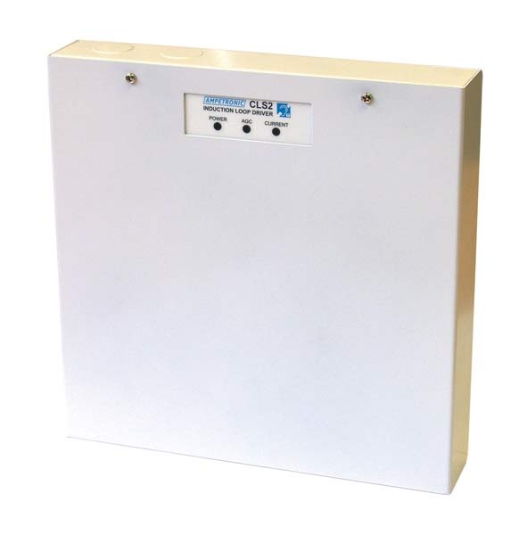
The CLS2 enclosure is designed for simple, permanent installation, with secure lid protecting connections and controls, while leaving operation indicators visible. The case is designed to make access simple, and to ensure the ampli er can be installed in the most constrained spaces.
Mounting
Designed for vertical panel mounting using 4 screws (6 holes provided). Template for screw placements provided. The CLS2 is compact enough to t on a 1U rack tray with feet removed.
Enclosure access
Hinged lid, secured by 2 Phillips PH2 screws. Lid can be removed completely if required, for ease of access, or if there is no room to hinge the lid forwards.
Cable routing
Knock-outs (diameter 20mm) are provided for routing cables into the enclosure. 2 on the top edge, 4 on the rear face, 4 on the bottom edge, providing excellent installation exibility.
Cable connections
All input cable connections are made with screw terminals mounted on one side of the PCB. Mains power connections are made to a chassis mounted screw terminal block. Loop connection is made to a screw terminal pair mounted on the PCB. Cable connections are illustrated on a detailed label on the case interior.
Indicators
3 LED indicators are visible with the case open or closed:
AGC Amber LED lit when input signal is activating the automatic
gain control
Current Green LED lit when current is running in the loop
Power Green LED lit when the unit has power
Controls
Five controls are located to be accessed only with the lid open, all screwdriver adjustable.
Level controls for inputs 1, 2, 3 and 4
Metal loss correction
Loop drive current
Issue no UP36401-4
Standards Compliance
The CLS1 is CE marked to all relevant safety and EMC standards, including EN60065 and EN55103. Safe operation is subject to correct installation. The CLS1 will meet the requirements of IEC60118-4 and the relevant recommendations of BS7594 if speci ed and installed correctly.